Conditions of Use
The first step in designing a generator system is to develop the programmatic requirements of the design. It is important to understand:
- What type of building will this serve? Will this be used for a mission critical application, hospital, industrial facility, or another type of load? The answers here will determine the codes and standards that apply to the design.
- How will the generator be used? For example:
– Is it used as backup power in the event of utility failure or will it provide power continuously throughout the year?
– How will the generator be operated? Is it a 100% standby application or will the onsite staff start the generator during rate curtailment or during a storm event?
– Will the loads be emergency, legally required, or optional standby as classified in Articles 700, 701, and 702 of the NEC?
- Site conditions:
– Ambient conditions: What is the maximum temperature of the cooling air as it enters the machine? National Electrical Manufacturers Association (NEMA) ratings are based on 104°F, so if the installation exceeds those limits, let the manufacturer know. Derating will be required.
– Altitude: Generators operating at about 3,281 ft. may need to be derated. Make sure to provide the altitude of the site to the generator manufacturer and take altitude into account when performing load calculations. Most manufacturers can provide derating factors for a given altitude.
– Are there any other site conditions that will impact generator operation, such as a corrosive environment, excessive humidity, or extreme cold
Fuel
The next question to ask is what type of fuel should be used for the application. The primary fuel types are diesel, natural gas, bi-fuel, and propane. Key points in deciding the fuel type include environmental considerations, code-required starting time, the availability of the fuel type locally, fuel storage, and the commercial availability of the generator size.
Diesel. Diesel is the most common generator for standby applications. Diesel generators are available from many manufacturers in a wide range of frame sizes. Diesel generators are reliable and economical, and the fuel is widely available and easily stored onsite. Diesel generators start quickly and accept large block loads with reasonable voltage dip. Those criteria are vital for emergency applications where the generator must start and accept load within 10 seconds (refer to NEC Article 700.12 and NEC Article 517) and the fuel system must have a reliable supply.
Diesel generator disadvantages include additional emissions, which may require additional equipment and fuel treatment. Additionally, diesel fuel does not store well over a long period, so a fuel-polishing system may be required.
Diesel fuel storage. Diesel fuel is stored either in base (belly) tanks (installed under the generator), day tanks (located near the generator and dedicated to the generator), or centralized storage. Base tanks are very simple to specify and generally do not require many external systems. Potential challenges with base tanks include coordination of underground conduits through the base-tank conduit window and increased engine height as the fuel-storage requirements increase. Day tanks also provide a simple solution, but do require additional space, additional piping, and auxiliary fuel pumps. They are more expensive to install and commission than base tanks. Centralized fuel tanks provide a central location for diesel fuel and are useful when large storage quantities are required. Centralized fuel tanks require a significant investment in additional piping, pumps, and fuel-polishing systems.
Natural gas. When compared with diesel, natural gas is clean-burning and has reduced emissions. Natural gas gensets are available in large frame sizes, are appropriate for base/continuous loads, and are less expensive than diesel when used continuously.
However, natural gas generators do not have the same transient response or acceptance of large block loads as diesel systems. Upon application of load, a natural gas generator must mix fuel and air, move it through the entire air-intake system, and then into the cylinder, which results in delayed voltage and frequency response. This, combined with a lack of onsite fuel storage, generally precludes the design engineer from applying them in emergency applications or for large block loads with fast start requirements. Many jurisdictions do not consider natural gas a reliable supply, so using natural gas as the only fuel most likely will not be allowed where backup power is required by code. That said, generator manufacturers are rapidly making improvements to natural gas generators to improve start time and load acceptance, with some manufacturers accepting 100% load within 30 to 40 seconds. As a result, natural gas generators are starting to be deployed as backup power in datacenter applications.
Bi-fuel. Bi-fuel generators combine some of the best features of diesel and natural gas generators. Typically, the generator will start on diesel and then introduce natural gas into the combustion airstream. The power of the generator is then provided through the combined combustion of as little as 30% diesel and as much as 70% natural gas. Note that these percentages depend on the manufacturer and the load profile that the generator supports. If natural gas is unavailable, the generator can run on 100% diesel. This system can result in lower emissions, fuel flexibility, and fuel storage that meets the requirements of NFPA 99 and NFPA 110.
Bi-fuel generators are not a standard offering of all major manufacturers, so specifying a bi-fuel generator may eliminate some manufacturers from bidding or require a third-party solution that modifies the generator. Purchasing a diesel generator and supplying natural gas to it also introduces an additional first cost.
Propane. Propane generators are good choices for small installations at remote sites or when other fuels may not be available. Propane generators are only available in relatively small sizes. The maximum size depends on the manufacturer, but they are generally limited to 150 kW and lower. Larger sizes are available, but are costly.
Propane fuel tanks can be located onsite and do not suffer from the “unreliable” fuel supply issue that sometimes limits natural gas generators. Propane is commonly used in urban areas as a backup to a natural gas where required by code, or on federal lands due to concerns with diesel spills. When selecting a propane generator, take special care in selecting the fuel vaporizer. Liquid vaporizers allow for smaller tanks and function better in cold weather, but may be a parasitic load on the generator. Vapor-based vaporizers pull the vaporized propane off the top of the tank. These systems are simple and require less equipment than liquid vaporizers.
Environmental
Environmental considerations include environmental tiers and requirements, airflow, noise, and indoor or outdoor installation.
Environmental tiers and requirements. The U.S. Environmental Protection Agency (EPA) tier requirements have impacted the purchase and operation of new diesel generators. For stationary emergency loads, the EPA allows non-Tier 4 generators to operate for an unlimited number of hours for an emergency condition and 100 hours/year for all other reasons. Generators meet the stationary emergency requirements if:
- They are permanently installed.
- Are used to back up permanently installed utility service.
- Only run during a power outage/loss of utility service.
The 100-hour limit must cover all testing and engine exercising and nonemergency uses. Additionally, only 50 hours of the 100 hours may be used for nonemergency purposes. Often, owners want to operate their generator during a nonemergency event, such as peak shaving, rate curtailment, or storm mitigation. The rules governing these uses are complicated, but peak shaving and rate curtailment are not considered emergency use, so a Tier 4 generator is required for these applications. For more information on this topic, please refer to the latest EPA guidance.
In addition to the EPA requirements, there are multiple agencies throughout the country that regulate the environmental impact of generator installations. Before assuming that an installation is acceptable, it is critical to work with the local authorities to understand their unique requirements.
For some installations, additional emissions control devices, such as selective catalytic reduction (SCR), may be required. Refer to the large black cylinders in the upper right of Figure 1. Note that the installation of SCRs will require additional space around the generator as well as the installation of an ammonia-injection system.
Airflow. Generators require air for both combustion and cooling. When designing a generator layout, it is an easy error to recirculate hot air and cause insufficient cooling of the generator. This can be particularly pronounced in multiple generator scenarios. Manufacturer application guides can provide detailed guidance. For large installations, computational fluid dynamics modeling should be performed, but the following suggestions are good practices:
- Locate inlets and exhaust away from each other and other sources of heat.
- Avoid stagnant air or entrainment of other exhaust streams.
- Exhaust the generator from the highest point of the installation.
- For outdoor installations, avoid installing generator systems in completely enclosed areas.
- For multiple-generator applications, model the airflow with all engines running and a partial set of engines running. The airflow internal to the room will be different and may result in overheating when only a subset of the generators is operating.
Noise. Noise is a concern for nearly all installations. Manufacturers measure generator dB at 23 ft (7 meters) from the generator. When specifying a generator set, there are two effective design approaches to mitigating noise issues:
- After performing a noise study, tell the generator manufacturer the dB level that is required at 23 ft from the generator. The three typical options are 85, 75, and 65 dBa. The lower the dB, the greater the sound attenuation and the greater the cost.
- Provide the generator manufacturer with the dB requirement at the property line and the position of the generator relative to the property line. With this information, the manufacturer can do the calculations and provide the necessary attenuation.
Indoor or outdoor installation. Where will the generator be located? If it is going to be indoors, make sure that you provide at least 3 ft of access on all sides and 5 ft of clearance from any combustible walls. Many jurisdictions require remote fuel-fill stations for indoor installations, which require controls, piping, and additional space. Indoor installations also must leave room for maintenance, code clearance around generator-mounted breakers, exhaust systems, air intakes, and other ancillary systems.
If the generator is located outdoors, the installation will require some sort of outdoor enclosure (see Figure 2). When located outdoors, additional conduits are required to provide auxiliary power to the generator set. Outdoor enclosures can be simple or may come with a full walk-in enclosure. A walk-in enclosure takes up considerably more space and costs more, but it may be an appropriate choice if additional room is needed for switchgear or if the climate makes working outdoors impractical.
Load
Generators are provided with continuous, prime, or standby ratings based on the ISO 8528-1 standard. Continuous ratings are the maximum power that the generator can supply to a constant load without run-time restrictions. Prime ratings are the are the maximum power that the generator can supply to a variable load without run-time restrictions. The average power output over 24 hours is limited to 70% of the prime rating unless there is other documentation from the manufacturer. Lastly, standby ratings are the maximum power that the generator can supply to a variable load for a maximum of 200 hours/year. As with the prime rating, the average power output over 24 hours is limited to 70% of the prime rating unless there is other documentation from the manufacturer. The generator type is selected based on the load profile that they are expected to support.
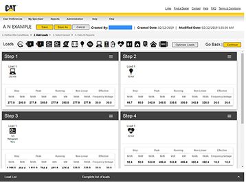
To determine the best generator type to support the building load, you must perform load and starting calculations and understand any special characteristics of the supported load.
The first step is to perform a basic generator loading calculation to determine the kW and kVA that the generator must support under steady state operation. In the past, these calculations were performed by hand, but now are typically performed using generator manufacturer software. If the generator is being used to back up an entire utility service, the generator size can be approximated based on the utility peak-demand data plus 25%. In addition to ensuring that the generator is large enough, it is important to make sure that it also is sufficiently loaded to avoid “wet stacking,” or a buildup of unburned fuel in the exhaust system. For more information, consult “A Close Look at Wet Stacking,” (Divine, 2010).
When performing load calculations and sizing generators, a few load types are particularly challenging for generators:
- High harmonics: If high-harmonic content loads are connected to the generator, this may necessitate oversizing the generator.
- Leading power factor: Input filters and lightly loaded electronics can result in leading power factor loads. Leading power factor is particularly difficult for generator-voltage regulators. If leading power factor is a potential concern, identify that at the time of specification. To mitigate the issue, input filters can often be disabled/bypassed during low-load conditions.
- Elevators: Elevators may provide a significant regenerative load. Many elevator controllers can now accept a dry contact input to indicate that the elevator is “on generator.” The elevator can then be reduced to half speed to limit the regeneration on the generator.
- Altitude: Refer to the section above and make sure to apply the manufacturer-supplied derating factors.
Load starting. A frequently missed calculation is the generator load-starting calculation. This calculation ensures that the generator is capable of starting all loads while staying within the required voltage and frequency requirements of the energized loads. Some loads, such as imaging equipment, have tight voltage and frequency requirements while other loads may be much more forgiving. To properly size the generator(s) based on the starting/inrush currents of loads, try the following:
- The most challenging starting condition for a generator is 100% block loading, so avoid this whenever possible. Break up the load into several load steps by using controls or an automatic transfer switch (ATS).
- Do not be overly conservative with voltage-dip requirements on starting. If the load can tolerate a 30% voltage dip, allow that. Specifying 20% voltage dip can result in an oversized genset.
- Start large motor loads first.
- Use variable frequency drives or reduced-voltage starting whenever possible.
- Use the “walk-in” feature of uninterruptible power supply systems that slowly transfers load from battery to generator.
Electrical System Configuration
Are you able to effectively serve the load with a single generator or do you require additional generators? Single-generator systems are relatively simple to design and are the most common configuration. If you can serve the load, does code or the business model require that there be a second generator? If you need an additional generator, you may need to parallel generators. Paralleling generators is a complicated topic that is beyond the scope of this article; please read “Paralleling Generator Systems” (Winter 2016) for additional information. Refer to Figure 4 for an example of a parallel generator system in a medical facility.
Moving Forward
Every generator system design has its own unique challenges. By using a systematic design approach, the key design elements can be determined by answering a few key questions. You must determine:
- The applicable codes.
- The generator rating and fuel type.
- The environmental conditions.
- The load profile and overall loading.
With those key elements decided, you can fully specify and design a code-compliant and successful generator installation.
Case Study: Medical Center
AECOM was retained to design a medical center that could be adapted in the future for use as a nonsurgical hospital. Consequently, the electrical system was designed as a hospital following Article 517 of the National Electrical Code (NEC). Refer to Figure 4 for the basic system topology. Note that the topology closely mirrors Informational Note 517.30 in the NEC. The medical center was built on a brownfield site, which also was in a flood plain. So, the ground level of the facility was planned for parking and the electrical service rooms were elevated above the level of the flood plain.
Codes and Standards
- NEC, primarily Articles 445 (Generators), 517 (Health Care Facilities), and 700 (Emergency Systems.
- NFPA 99: Health Care Facilities Code.
- NFPA 110: Standard for Emergency and Standby Power Systems.
Conditions of Use
This was designed as a health care facility per NEC Article 517. Because many of the loads were noncontiguous, standby-rated generators were used.
Fuel
Both generators use diesel, although bi-fuel was considered. Diesel was the most appropriate choice due to efficiency, given the size of the generators and the ability to easily store the code-required fuel. Bi-fuel was removed from consideration due to cost and constructability concerns.
Environmental
The generators are used for emergency use, so Tier 4 generators were not required. The generators were installed indoors and inside the building footprint (see Figure 3). The generators were placed indoors to:
- Minimize the amount of campus real estate used.
- Assist with noise abatement. The installation is in a controlled area with tight noise restrictions. Critical generator silencers were provided on the generators and as well as noise baffling in the walls to assist with both external noise and noise transmitted internally to the medical center.
Load
This is a standby application with variable loading, so 800-kW standby-rated generators were used. At the time of commissioning, only one generator was required to support the load, so the generators were an N+1 configuration (see Figure 4). As the rest of the facility is fit out, both generators will be required to supply the load. Two generators were installed, rather than one larger generator, to avoid low-load operation and its resulting maintenance issues, such as wet stacking, during the initial phases of the project.
To confirm that the generator system could start the loads, generator manufacturer starting software was used. The energization of loads on the generator plant influenced several design components. The automatic transfer switch (ATS) system was designed with delays matching the requirements of NEC Article 517 (see figures 4 and 5).
The building contained many high harmonic loads and included medical-imaging equipment including X-ray, CT, and MRI. These were characterized using vendor software to confirm that the generator system was properly sized. Additionally, in the original design, the MRI room was in relatively close proximity to electrical rooms. As the design developed, the MRI rooms and the electrical rooms were moved a greater distance apart, and additional shielding was added to the MRI rooms to avoid adverse effects from the magnetic fields produced by the imaging equipment. The shielding design was performed by a design firm that specializes in the analysis and specification of shielding.
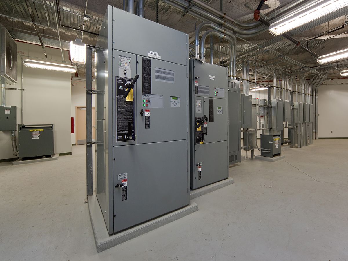
Electrical System Configuration
Because the facility was designed to be a future hospital, the electrical system was configured to include equipment, life safety, and critical ATSs, with the life safety branch, then critical branch, then equipment branch transferring to the generator. The terms “life safety branch,” “critical branch,” and “equipment branch” are defined in NEC Article 517. The generator vendor supplied the paralleling switchgear, ATSs, and generator protection. The protection scheme provided with the generator was used to provide generator overload protection and selectivity rather than relying on the generator output breaker for this protection.
Brian Martin is a senior electrical engineer, buildings and places, with AECOM. He has more than 20 years of experience in engineering planning, project management, design, purchasing, and start-up of industrial projects. He is a member of the Consulting-Specifying Engineer editorial advisory board.